What is Faraday shield
Faraday shield
 Isolation transformers constructed with Faraday shields, will improve power quality by attenuating higher frequency noise currents. Isolation transformers provide better impendance matching of a critical load to an electrical circuit . Internal low-impedance isolation transformer component offers 100% isolation from the input AC line. Hospital Grade Isolation transformers is ideal for the protection of sensitive electronic equipment in patient-care areas. Isolation transformer with Faraday shield reduces the cumulative leakage current of the Isolator and connected equipment to levels below 300 microamps.
Surge suppression components placed at the line input and output combined with full line isolation offers continuous filtering of a full range of power line noise in all modes. Active transformer filtering offers continuous common-mode noise rejection with no wearable parts, uniquely able to reduce surges in the worst of power environments to harmless levels. isolation transformer provides a "code-legal" method of re-bonding the electrical system safety ground to the neutral conductor on the transformer secondary. Doing so eliminates neutral-to-ground voltage and noise, which is major cause of reliability problems for microprocessor-based electronics.
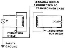
In electronics testing, troubleshooting and servicing, an isolation transformer is a 1:1 power transformer which is used as a safety precaution. Since the neutral wire of an outlet is directly connected to ground, grounded objects near the device under test (desk, lamp, concrete floor, oscilloscope ground lead, etc.) may be at a hazardous potential difference with respect to that device. By using an isolation transformer, the bonding is eliminated, and the shock hazard is entirely contained within the device. Isolation transformers are commonly designed with careful attention to capacitive coupling between the two windings. This is necessary because excessive capacitance could also couple AC current from the primary to the secondary. A grounded shield is commonly interposed between the primary and the secondary. Any remaining capacitive coupling between the secondary and ground simply causes the secondary to become balanced about the ground potential.
All transformers provide isolation. They are constructed with a primary and secondary winding closely wrapped around the same ferrous core. Commercial transformers incorporate a single Faraday shield between the primary and secondary windings to divert noise, which would normally be electrically coupled between the primary and secondary windings to ground . The method through which this electrical coupling of noise occurs is the capacitance between the coils of the primary and secondary windings of the transformer, which does not include a Faraday shield. This same capacitance limits the upper frequency band pass of the transformer in the same manner as the mutual and self-inductances of the device determine its low frequency cutoff. As the frequency of the exciting currents increases, the reactance caused by the capacitance between the windings, tends to shunt these currents, thereby limiting high frequency performance.
The single Faraday shield controls all manner of evils which could be attributed to the electric coupling of noise through a transformer. However, the problem with a single shield arises when it is bonded to the ground of either the primary or secondary side of the transformer. The enclosure of a Faraday shield between the primary and secondary windings eliminates inter-capacitance, but it also establishes two new capacitances between the shield and both windings. These two capabilities allow high frequency currents to flow in the grounding systems of both the primary and secondary. Bonding the transformer shield to either the primary or secondary ground establishes current paths for high frequency noise in the reference conductor of the circuit to be isolated. The particular choice of ground for connection of the shield only provides selection of the quieter of the primary and secondary circuits. In many applications, this current path defeats any isolating effect, which a transformer might provide.
- ❮Go back to the previous page.
- Use the search bar at the top of the page to search for your products.
- Follow these links to get you back on track!
Store Home | My Account

 United States