Isolation Transformer
What is Isolation Transformer?
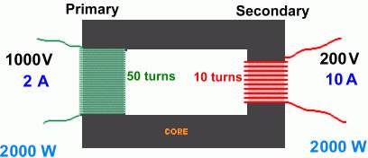
Isolation Transformers have primary and secondary windings that are physically separated from each other. Sometimes isolation transformers are referred to as "insulated". This is because the windings are insulated from each other. In an isolation transformer the output winding will be isolated, or floating from earth ground unless bonded at the time of installation. Secondary neutral to ground bonding virtually eliminates common mode noise, providing an isolated neutral-ground reference for sensitive equipment and an inexpensive alternative to the installation of dedicated circuits and site electrical upgrades.  An isolation transformer allows an AC signal or power to be taken from one device and fed into another without electrically connecting the two circuits. Isolation transformers block transmission of DC signals from one circuit to the other, but allow AC signals to pass. They also block interference caused by ground loops. Isolation transformers are different from auto transformers in which the primary and secondary share a common winding. Isolation transformers are often used to protect high gain circuits, or prevent noisy ground paths in instrumentation. Shielding at the instrument level is difficult and often ineffective. Since most commercial instrumentation has single shielding in its power transformer, designers sometimes hope that by adding a isolation transformer ground problems can be eliminated. This approach often results in no benefits to the system unless all other ground paths in the instrument can be totally isolated. An isolation transformer is not a substitute for the proper shielding or grounding of individual instruments. The amount of ground isolation provided by the transformer at the box level is limited by the use of a single chassis shield enclosing the box. High frequency noise currents generated by the box circuitry can be coupled onto the circuit reference conductors through the connection of both transformers' shields to the circuit reference. Additionally, any potential difference between the power system ground at the isolation transformer primary input and the power system ground at the equipment and the power system ground at the equipment chassis will cause currents to flow in the reference conductor of circuitry. Three phase Isolation transformers are used for many applications ranging from grain dryer, saw mills, conveyor belt systems, refrigeration and air conditioning. Three phase have 3 primary and 3 secondary windings that are physically separated from each other. Each of these windings are insulated from each other. The output windings will be isolated, or floating from earth ground unless bonded at the time of installation.
- Go back to the previous page.
- Use the search bar at the top of the page to search for your products.
- Follow these links to get you back on track!
Store Home | My Account

 United States